
PID based Feedback Control of DC Motor
One of the fundamental aspects of robotics is motor control. This project uses the PIC32MX250F128B microcontroller mounted on board the NU32 board and MATLAB based GUI for desired angle for the motor.
HARDWARE
- Brushed DC motor
- Motor encoder
- NU32 microcontroller board
- Quadrature encoder counter
- MAX9918 current-sense amplifier
- DRV8835 H-bridge
- 6V battery pack
- Resistors and capacitors
SOFTWARE
The controller uses two feedback loops:
- inner high-frequency 5kHz current controller that controls the PWM output to the motor
- outer low-frequency 200Hz position controller that controls the motor

CURRENT CONTROL
The output torque of the motor is drectly proportional to the current. Therefore we change the amount of current into the motor and control the torque and speed ofthe motor. This process can be done by seeing the duty cycle of a PWM signal corresponds to the desired torque. The MAX9918 current-sense amplifier is used to read the current at any given moment - specifically, it reads the current at 5kHz for the control loop, and a PI controller is implemented to set the right duty cycle.
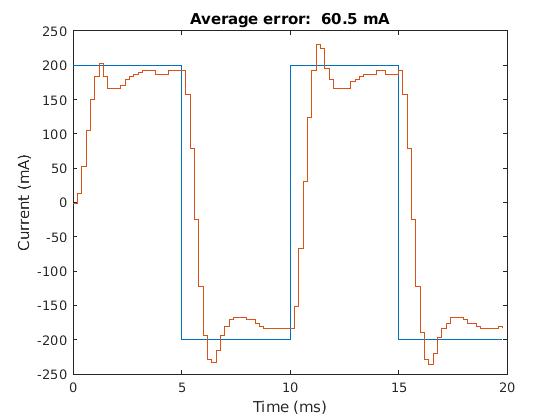
(Performance of the current control)
POSITION CONTROL
A PID controller is used for position control. It uses encoder information to determine how far the motor is from its desired postion and calculates the required current needed to bring the motor to that position.

(Step Trajectory)
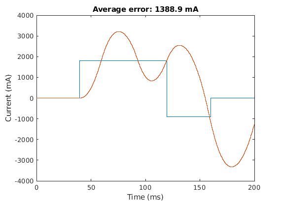
(Performance of the position control for a step trajectory)

(Cubic Trajectory)
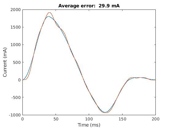
(Performance of the position control for a cubic trajectory)
(Feedback Control Bring the Motor Back to the Desired Position)