
Mechatronics with PIC32
PIC microcontrollers ( Programmable Interface Controllers), are electronic circuits that can be programmed to perform various tasks. This post includes some mechantronics tasks with PIC32 Mictrocontroller and MPLAB IDE. You can check out the source codes at my Github
Voltage Regulator and Basic PIC32 Circuit
We have 5V between the VBUS and GND pins. Using VBUS as the input to the pololu, we can get 3.3V out. Add a red LED in series with a 330 ohm resistor to the 3.3V output voltage, and check the voltage again. We’ll use 3.3V and ground a lot, so make the rails on your breadboard 3.3V and ground according to the color code on the breadboard.
Circuit Construction Procedure:
- Connect all VDD pins to 3.3V, all VSS pins to GND. Each VDD pin gets a 0.1uF or 1uF capacitor to GND (either value works). The capacitor is supposed to be as close to the pins as possible, to suppress noise that might make the PIC turn off if the power line fluctuates.
- Connect the VCAP pin to a 10uF capacitor to GND, note that the 10uF capacitor is polarized.
- Use the long header pins to connect the MPLAB Snap programmer to the breadboard. Pin one of the Snap is labeled with a black triangle. Connect the Snap - VDD to 3.3V and GND to GND. Connect PGD to PGED1 and PGC to PGEC1 of the PIC. Connect the Snap MCLR to MCLR of the PIC.
- Connect MCLR to a 10k pull-up resistor and a pushbutton to GND, this is the Reset button.
- Connect the PIC OSC1 and OSC2 pins to the outside pins of the 8MHz resonator, and the center pin of the resonator to GND. The wires that connect the resonator to the PIC should be the same length and the resonator should be as close to the PIC as you can make it. These are the minimum connections necessary to make the PIC work, but with no inputs or outputs it is hard to tell, so we’ll add an LED and a User button.
- Connect pin A4 to a green LED to a 330 ohm resistor to GND.
- Connect pin B4 to a 10k pull-up resistor and a pushbutton to GND.
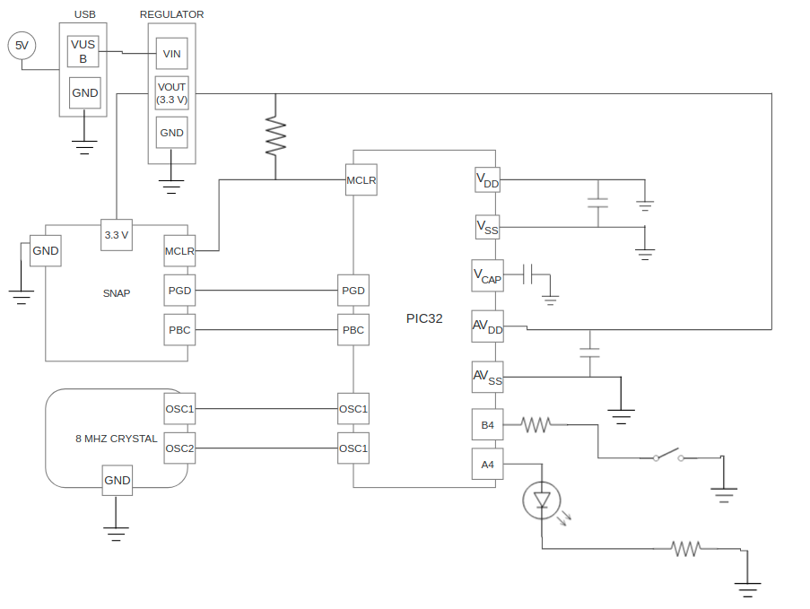
Circuit Diagram
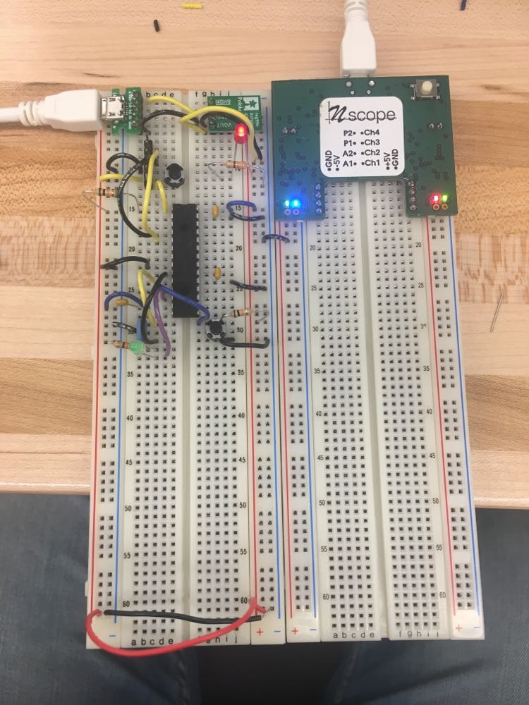
Circuit Image
MPLAB IDE provides programming enviroment and communication to the PIC32. We will make a circuit which initializes B4 as input and A4 as output that is initially off. In the infinite loop, if the value of B4 is pushed, turn on A4 for 0.5s, off for 0.5s, on for 0.5s, and off for 0.5s (so two one-second square wave blinks)
Demo
Universal Asynchronous Receive and Transmit
The PIC that we are using does not have a USB peripheral, so we have no way of communicating with our computer directly. The Snap programmer has debugging capabilities, but no generic data transfer method. To get data back and forth, we will use a USB to UART converter chip from Adafruit. Adding the Adafruit CP2104 Friend USB to UART converter allows communication of the PIC32 with the computer.
Demo
Serial Peripheral Interface
The Serial Peripheral Interface (SPI) allows the PIC32 to communicate with other devices at high speeds. Numerous devices use SPI as their primary mode of communication, such as RAM, flash, SD cards, ADCs, DACs, and accelerometers. We generated a 2Hz sine wave and a 1Hz triangle wave. Both range from 0V to 3.3V.
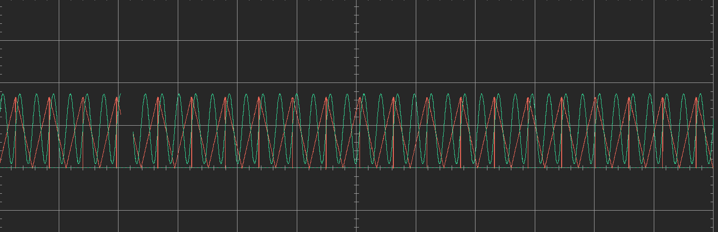
Result
ST7789 Display
An LCD is a two dimensional array of pixels used to display data. Each pixel has three little screens, tinting the light that passes through them red, green, and blue. A white backlight behind all of the pixels passes through the screens, creating the color you see. We will use a 240 x 240 pixel IPS LCD, 1.8 inches diagonal, communicating using an adjusted type of SPI. The LCD has a built in controller, a ST7789. With the highest color depth resolution (2 bytes per color), it takes 240 x 240 x 2 = 115200 bytes of data to fill the screen.
We will Create an algorithm to take an ascii character, like ‘H’ (also represented by decimal 72), and draw it so that the top left corner is at any pixel location, using LCD_drawPixel to write the ASCII matrix contents to the LCD. When we have written a function that can draw one character to the LCD, we can make a char array with sprintf(), and call the function in a loop to display every character in the string. Fianlly, We will have a LCD showing “Hello world %d!” starting at (28,32), and below it a progress bar with the length of the displayed integer. Increment the integer from 0 to 100 at 10Hz, or as fast as it will go, displaying the live FPS.
Demo
WS2812B Neopixels
To add a little color to our circuit we’ll use some WS2812B addressable color LEDs in an 8mm package from Sparkfun. The WS2812B is also called a Neopixel and comes on sticks, rings, matrices, and infinitely long lengths of flexible tape. Traditional color LEDs are very pin intensive. Each LED is really a red, green, and blue LED cast inside the same plastic lens. Each needs to be set for intensity using a unique PWM, and a microcontroller like the PIC32MX170F256B has only 5 PWM pins, so it couldn’t even drive 2 LEDs. Other brands of microcontrollers have many more PWM capable pins, but even then it would take a lot of multiplexing to drive a lot of color LEDs.
WS2812B are a nice solution. They have a built-in controller that takes a single digital signal to set the brightness of the red, green, and blue LEDs, and if you immediately send another color, the data is passed-through to the next WS2812B. That means you can chain WS2812Bs in series and control each color and brightness uniquely with only one pin from the microcontroller.
ws2812b_setColor() is the main function. The function takes as input an array of colors and the number of WS2812Bs in the circuit. In the function, you need to loop through each pixel in each color, and into another array, save the time in Timer2 ticks at which the pin should invert to blink out the highs and lows to make the logic Ones and Zeros. Once this array is made, it is a simple process to set Timer2 to start at 0, and inside a loop wait for the timer value to hit each array value, and when it does invert the pin. The while loop adds some extra cycles, which could knock the timing off, so the LOWTIME and HIGHTIME constants are adjustable. Once we can set the colors, use the HSBtoRGB() function to generate a changing array rainbow of colors to display on your LEDs.

Demo
Inertial Measurement Unit
An IMU, or inertial measurement unit, is a sensor that is used to calculate position, velocity, or acceleration. Modern IMUs are MEMS devices, with built in analog to digital converters, and their own dedicated microcontroller to control and process the data. Common IMUs combine accelerometers, gyroscopes, magnetometers, and altimeters. Often they come packaged together in a single chip. The sensors typically communicate over I2C or SPI.We will use the LSM6DS33 accelerometer and gyroscope chip made by ST, soldered onto a breakout board by Adafruit.
This chip measures acceleration (accelerometer) and angular velocity (gyroscopic) data about the X, Y, and Z axes with 16 bit resolution, with a variety of sensitivities. It contains a temperature sensor so that it can self correct for temperature effects, and we can also access the temperature data as a 16 bit number.