[CAN 04] - Gripper Motor Control with CAN Bus
Single Motor Control with ESP32, simpleFOC, and SocketCAN for Robotic Gripper
Code: [GitHub]
Previous Posts:
In the previous posts, we have achieved communicating setting up SocketCAN on Ubuntu and communicating with ESP32. In this post, we will control 1-DOF roboric girpper with ESP32 and SocketCAN using SimpleFOC Arduino library.
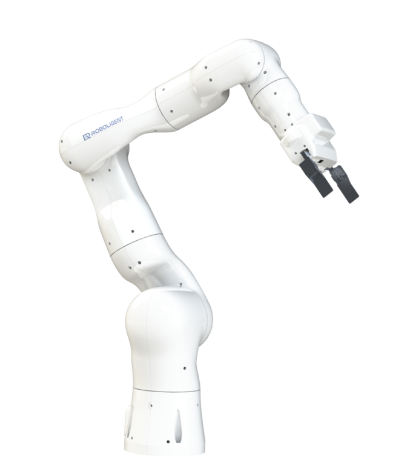
This is a collaborative work Roboligent with their robot manipulator, Optimo.
Hardware


- SimpleFOC Mini
- HT2205 with AS5048A Encoder Onlly used for testing not for the gripper
- TJA1050 CAN Transceiver
- ESP32 Dev Board
- Makerbase CANable 2.0 USB to CAN adapter
Wiring

-
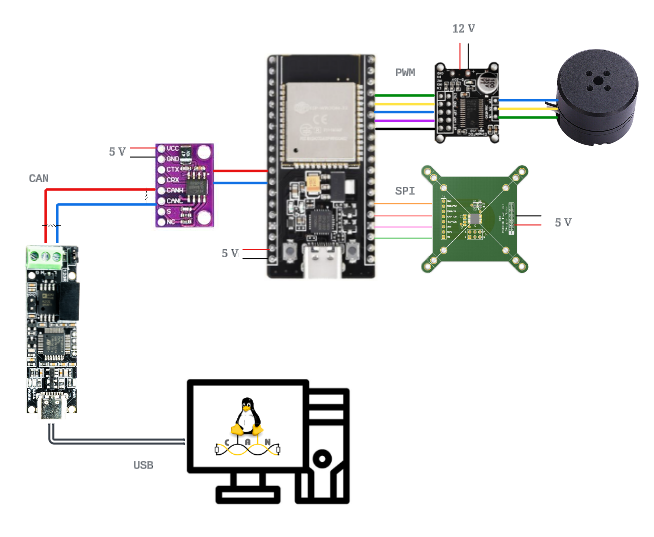
The wiring for ESP32 and CAN Transceiver is same as the previous post. Some TJA1050 CAN Transceiver modules and USB-CAN deviuces include internal 120 ohm termination resistor. If you are unsure, measure the resistance between CAN-H and CAN-L wires to ensure it’s reading 60 ohm.
-
Connect the BLDC motor’s u, v, w phases to the SimpleFOC Mini boards’ M1, M2, and M3 pins. The phase order does matter. If they are in a wrong order, the motor will not commmutate properly or run in the opposite direction. SimpleFOC Mini board will need a separate power supply. I will be providing 12 V to control HT2205 motor.
-
Connect IN1, IN2, IN3, and EN pins to ESP32 GPIO pins while GND connects to the ground of ESP32.
-
Supply 5V to SPI encoder and connect the SPI pins to ESP32. Most ESP32 have pre-assigned default SPI pins, but these pin assignment can be different depending on the board. You can check the default SPI pinout of your ESP32 board from the following code:
void setup() {

  Serial.begin(115200);
  Serial.print("MOSI: ");
  Serial.println(MOSI);
  Serial.print("MISO: ");
  Serial.println(MISO);
  Serial.print("SCK: ");
  Serial.println(SCK);
  Serial.print("SS: ");
  Serial.println(SS);
}

void loop() {
}
-
Make sure that there is a proper airgap between the motor magnet and the encoder if you are using magnetic encoder. The recommended airgap is usually specified in the encoder datasheet. The typical airgap for AS5048a is 1 mm airgap, but it depends on how the strength of the magnet. Improper airgap can cause noise in the signal and faulty readings.
-
If you are trying to configue multiple SPI encoders with a shared bus (same MOSI, MISO, SCLK) but differnt chip select pins (CS), the physical wire lengths significantly affect the signal integrity. The longer the wire, the more the signal degrades. From my exerience, 3 SPI devices on the same bus with 80 MHz CLK had a maximum of 10 cm wire length. If you are using a longer wire, you may need to reduce the SPI CLK frequency. If you are 2 SPI devices, I recommend separating the SPI bus since ESP32 provides 2 SPI interfaces. You can more information here.
-
Flashing the Arduino Code
Make sure to install SimpleFOC and Arduio-CAN libraries for Arduino IDE.

The host computer will send the desired torque command in double format to the ESP32 via CAN bus. The ESP32 will receive the torque command and send the current motor position in double back to the host computer.
Since the CAN data can hold up to 8 bytes, we can directly encode the double data of torque command or motor position into the CAN data buffer with LSB order. Function such as std::memcpy for C++ or memcpy in Arduino will take care of packing the double data into the 1 x 8 byte buffer. However, make sure to check the endianness of the data to make sure the data is packed in LSB order.
void packDouble(double data, uint8_t *dataBuffer) {
    memcpy(dataBuffer, &data, sizeof(double));
}
Otherwise, we can directly allocate each byte of the double data into the CAN data buffer like this:
void packDouble(double data, uint8_t *dataBuffer) {
    uint64_t dataAsInt = *reinterpret_cast<uint64_t*>(&data); // Reinterpret the double as a uint64_t
    dataBuffer[0] = (uint8_t)dataAsInt;
    dataBuffer[1] = (uint8_t)(dataAsInt >> 8);
    dataBuffer[2] = (uint8_t)(dataAsInt >> 16);
    dataBuffer[3] = (uint8_t)(dataAsInt >> 24);
    dataBuffer[4] = (uint8_t)(dataAsInt >> 32);
    dataBuffer[5] = (uint8_t)(dataAsInt >> 40);
    dataBuffer[6] = (uint8_t)(dataAsInt >> 48);
    dataBuffer[7] = (uint8_t)(dataAsInt >> 56);
}
which is not clean but safe way to pack the data.
When a command is recived from the host computer, the ESP32 will send command current to motor by converting the torque command to current command with pre-defiend torque constant and respond with the motor position to the host computer.
We can implement a simple C++ code to read and write over SocketCAN to control the motor.
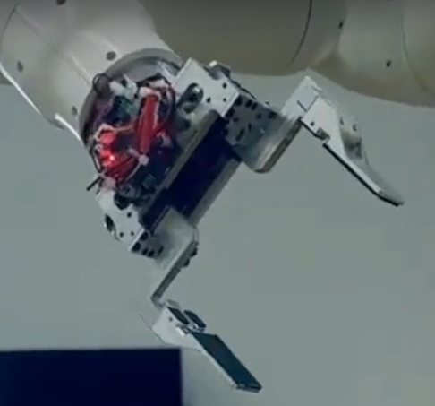
Now we can control the gripper motor using the same setup.
Using the linear motion of the belt, we can achieve parallel gripper motion. The belt is connected to the motor shaft and the gripper jaws. When the motor rotates, the belt moves the jaws in the opposite direction.

We recorded the joint trajectories including the gripper motor to push the jenga piece and grab it by kinestheic teaching (manually driving the robot). We can use the recorded joint trajectories to replay the same motion.

