[CAN 01] - What is CAN?
What is CAN Bus and how is it used in robotics?
Introduction
What is Control Area Network (CAN)?
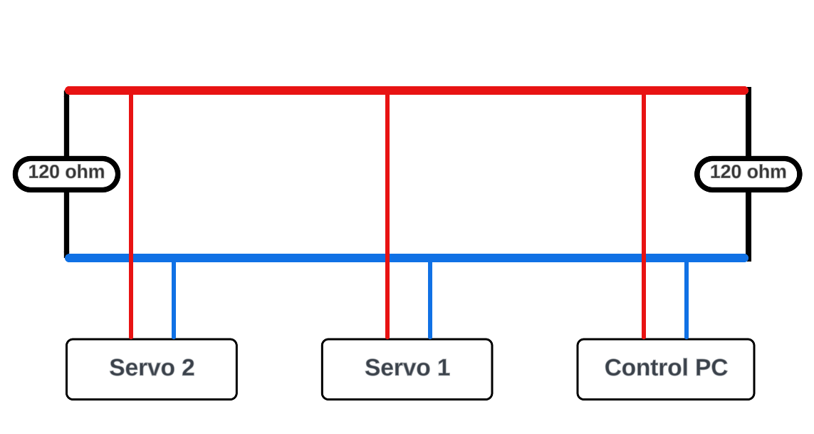
CAN is a communication interface widely used in the automotive industry due to its safety and reliability. CAN allows multiple electronic devices such as sensors and motor controllers to communicate in real-time via shared bus in which distributed CAN Nodes communicate through without a “master device”. CAN is a robust communication interface which can tramsits data over a long distance from 40 meters to 1,000 meters depending on the baudrate in hard coniditon subject to noise, interference, temerature, vibration, etc.
How is it used in Robotics?
In robotics, the Controller Area Network (CAN) is widely adopted for real-time communication between a host computer and motor driver modules. For complex robots like multi-DOF manipulators or legged robots, each motor driver module typically includes a microcontroller running control algorithms, such as Field-Oriented Control (FoC), to accurately control BLDC (Brushless DC) motors. In this setup, the microcontroller in each motor module calculates the PWM (Pulse Width Modulation) signals needed to control motor phases and achieve the desired movements. These PWM signals are then sent to motor drivers, such as the DRV8313, which uses them to drive the motor’s three phases. The control loop for each motor typically runs at a high frequency over 1 kHz, and a lot of motor driver modules such as ODrive, Mjbots, etc. include CAN controller and transceiver to enable the communication between the microcontroller and host computer.

The CAN bus can also support real-time, high-frequency impedance control by closing the control loop through the CAN bus itself, rather than solely relying on the control loop inside the microcontroller in the driver module. Impedance control plays a crucial role for robots that need to adapt their flexibility when interacting with dynamic environments or external forces. This adaptability is especially valuable for legged robots that frequently make and break contact with the environment. Impedance control allows these robots to safely absorb impact upon contact. Legged robots can navigate challenging terrains, avoid obstacles, and maintain balance by constantly adjusting their feed-forward torque and impedance gains.
\(\tau = M(q)\ddot{q} + D(\dot{q}_{d} - \dot{q}) + K(q_{d} - q) + g(q)\)
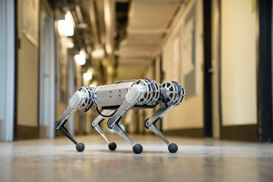
For example, MIT mini cheetah robot uses CAN bus to communicate with the motor driver modules to achieve real-time impedance control.

This awesome open-source quadruped robot’s communication structure have been adopted by many other actuators and robot companies.
Limitation of CAN Bus in Robotics
Mini Cheetah has 4 CAN channels while 3 motors are connected to each channel to control total 12 motors. This is one of the limitation of using CAN bus for real-time control robots. The maximum baudrate of CAN bus is 1 Mbps, and the bus can be easily overloaded when the number of motors increases in high control frequency. Assuming the control loop is running at 1 kHz with a tyical non-RTR standard CAN frame with 11 bits of data, the CAN bus is populated with 22,000 bps with command frame and response frame of a single actuator. This is approximately 22.2% of the 1 Mbps CAN bus. Since it’s recommended to keep the CAN bus load less than 70~80%, the maximum number of actuators that can be connected to a single CAN channel is 3. Decreasing the control loop frequencty will reduce the load on the CAN bus, but lower control loop frequency will not only reduce the performance but also increase the instability of the robot.